1, three phase inverter circuit Three phase inverter circuit diagram Three phase inverter circuit diagram
120° Mode Inverter – Circuit Diagram, Operation and Formula
Inverter phase circuit three 120 mode degree conduction diagram dc dilip raja nov Phase inverter voltage schematic circuit three source generator wiring diagram file Inverter wiring thyristor diode conduction
Phase inverter circuit signal three driver generator circuits diagram bridge homemade make
120° mode inverter – circuit diagram, operation and formulaPhase inverter circuit three homemade diagram circuits generator signal make mosfet oscillator using single driver projects simple bridge wave volt Three-phase inverter circuit.Circuit diagram of three phase inverter and load.
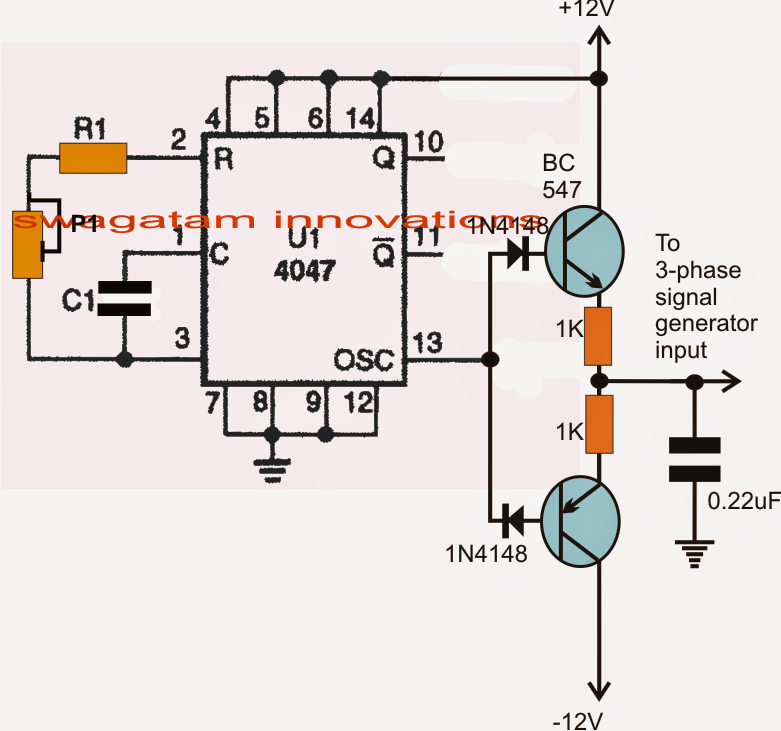
Inverter phase circuit basic basics ac working vfd drive principle variable frequency three figThree phase inverter circuit Inverter : operating principle,circuit, classification and applicationsMake this 3 phase inverter circuit.

Make this 3 phase inverter circuit
Phase three gate inverter ti inverters isolated drivers industrial vfd robustness interlocking improving schematic 3phase figure technicalInverter load Make this 3 phase inverter circuit3 phase inverter wiring diagram.
Inverter solar invertor pwm trifazic circuits 380v mosfet panouri 12v fasa tl494 integrat baterie solare electrica scheme method iulieSimple 3 phase inverter circuit Phase inverter circuit simple homemade circuits three driver arduino make using diagram ac projects solar ic bridge electronics based makingInverter phase circuit three diagram diy project projects.
Inverter phase circuit synchronized 4kva stackable lm324 circuits homemade three inverting non part four their make opamps above figure separate
Designing 1kw sine wave inverter circuitInverter mosfet circuits Three phase inverter circuit diagram – diy electronics projectsThree-phase inverter circuit..
Inverter phase circuit three diagram principle classification3 phase inverter wiring diagram Inverter classificationPhase inverter circuit circuits three generator homemade simple diagram wave push pull single arduino 4047 motor power driver control using.

Wiring diagram generator 3 phase
Three phase inverter circuit inverters open switchesVariable frequency drive basics (working principle) Make this 3 phase inverter circuitThree-phase inverter circuit with current and voltage measurements.
Three phase invertersThree phase inverter circuit Circuit diagram of a three-phase utility-interactive inverterThree phase inverter circuit diagram – diy electronics projects.

Phase inverter circuit three driver bridge circuits diagram mosfet line tweet half rail ics make
Phase circuit inverter three generator signal converters pwm diagram shiftedThree phase inverter schematic Inverter measurementsSimple 3 phase inverter circuit.
Interlocking gate drivers for improving the robustness of three-phaseMake this 3 phase inverter circuit Three phase inverter circuitInverter circuit sine wave diagram board schematic projects power electronics solar arduino inverters using diy ic 50hz charger output square.

Phase inverter circuit degree three diagram mode switches using conduction switch open cumbersome thyristor working than
Inverter circuit diagram mode 120 operation phase three bridge power figure formula electrical shown belowInverter circuit sine wave phase cascaded step diagram level simple homemade three frequency make construction test report multilevel will circuits Phase circuit three inverter circuits generator converter homemade simple processor incorporate stages regarding basic discussion following learn let these first.
.


Variable Frequency Drive Basics (Working Principle)

Three phase Inverter circuit | Download Scientific Diagram

Three-phase inverter circuit. | Download Scientific Diagram

Designing 1kW Sine Wave Inverter Circuit | PCB Design Full Guide

Three Phase Inverter Circuit | Circuit Diagram Centre

120° Mode Inverter – Circuit Diagram, Operation and Formula